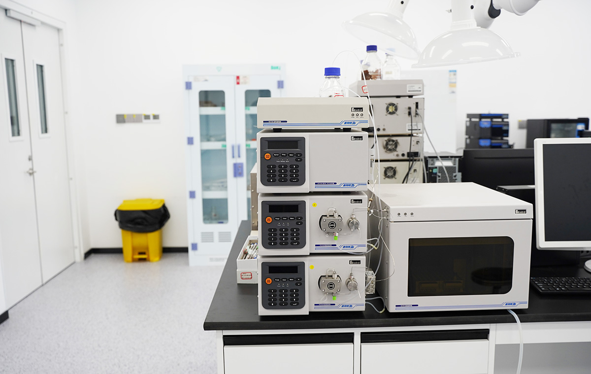
Liquid chromatography, with their advantages of high separation efficiency and precise analysis, have become core equipment in fields such as teaching and research, pharmaceutical production, environmental monitoring, food testing, and bioengineering. Correct operation of the instrument not only ensures the reliability of analytical results but also extends the service life of the equipment. This article details the complete operating procedure for liquid chromatography and provides solutions to common problems encountered in practice, offering a practical reference for professionals in relevant fields.
I. Standard Operating Procedure for Liquid Chromatography
(1) Mobile Phase Preparation
The purity and handling quality of the mobile phase directly affect the analytical results. Prepare the required mobile phase according to the experimental protocol, e.g., a methanol‑water mixture (e.g., 8:2 by volume), and also have sufficient pure methanol ready. All solvents must be filtered through 0.45 μm or 0.22 μm membranes to remove fine particles; then sonicate to thoroughly degas the dissolved gases, avoiding tubing blockages or baseline abnormalities in subsequent operations.
(2) Start‑up and System Preparation
Turn on the pump power, first set the instrument pressure upper limit (for conventional HPLC, typically set to 40 MPa); if already set, proceed to the next step.
Place the pump’s inlet filter into pure methanol, set the flow rate to 1 mL/min, and flush the system for 10‑20 minutes. After flushing, stop the pump.
Switch the filter to the prepared target mobile phase and restart the pump to circulate the mobile phase through the system.
Turn on the detector power, set the wavelength according to the analytical requirements (e.g., 280 nm for organic compounds), and press the “Zero” button to calibrate the baseline, ensuring accurate detection data.
(3) Workstation Start‑up and Baseline Monitoring
Start the chromatography workstation and check that the interface shows successful communication between the instrument and the workstation. Continuously observe the baseline; when the baseline becomes stable without obvious fluctuations, the system is ready for injection.
(4) Injection Operation
Before injection, confirm that the baseline is within the normal display range; if it exceeds the range, re‑zero.
Set the injection valve to the “LOAD” position, inject the standard or sample using a microsyringe, then quickly turn the injection valve to the “INJECT” position. The workstation will automatically start data acquisition.
After all chromatographic peaks have fully appeared on the chromatogram, click the “Stop” button in the workstation to end data acquisition.
(5) Calibration Curve Establishment (for quantitative analysis)
Set quantitative parameters: In the workstation, select “Quantitative Parameters”, choose “Peak Area” as the quantification mode, “External Standard Method” as the quantification method, set the number of calibration points to “1”, the power to “1”, and specify the concentration unit and result unit.
Fill in the component table: Enter the “Component Table” interface, input the name of the analyte (e.g., capsaicin in food testing), expected retention time (e.g., 5.2 min), and standard concentration (e.g., 100 μg/mL).
Generate the calibration curve: Click the “Calibration Curve” function, select the corresponding spectrum file for each standard point, click “Recalibrate” to generate the curve, confirm that the curve is linear, and save the settings for subsequent quantitative sample analysis.
(6) Sample Analysis and Data Review
Repeat the injection procedure for the test samples, stop data acquisition after all chromatographic peaks have eluted. Click “Screen Report” in the workstation to view the analytical results, such as the content of the target component in the sample. To analyse multiple samples, repeat the same steps sequentially.
To review historical data, enter the “Reprocessing” interface, select the corresponding spectrum file via “Open Data File”, click “Recalculate”, and then view the “Screen Report” to obtain the previous analytical results.
(7) Shutdown and System Maintenance
First, turn off the detector power to prevent damage from subsequent operations.
Stop the pump. If the mobile phase contained a buffer salt (e.g., phosphate, acetate), first place the filter into a high‑aqueous phase (e.g., 90% water), start the pump, and flush the system for at least 30 minutes to thoroughly remove salt residues from the tubing and column. Then move the filter to pure methanol and flush at 1 mL/min for 10‑20 minutes until the system pressure stabilises.
Stop the pump, turn off the pump power, and the computer may be turned off.
Finally, clean the injection valve with pure methanol or pure water to remove residual sample, completing the shutdown procedure.
II. Frequently Asked Questions (Q&A) about Liquid Chromatography
Q1: Why must the mobile phase be filtered and sonicated before use?
A1: Filtration removes fine particles invisible to the naked eye, preventing them from clogging the column frit and tubing, which would affect normal system operation. Sonication degasses dissolved gases (oxygen, nitrogen, etc.) from the mobile phase, preventing these gases from forming bubbles in the pump (causing pressure fluctuations) or interfering with the detector signal (causing baseline noise or ghost peaks).
Q2: After starting the pump, the pressure is abnormally high. What could be the cause?
A2: There are four common causes: 1) The column or tubing is blocked by accumulated impurities. 2) The mobile phase was insufficiently filtered, leaving particles to accumulate in the system. 3) The guard column or in‑line filter is saturated with adsorbed impurities. 4) The pump flow rate is set too high, exceeding the system’s tolerance. To locate the problem, disconnect the column inlet, start the pump, and observe whether the pressure drops – this helps determine whether the blockage is in the column or in the upstream tubing.
Q3: After starting the pump, the pressure is abnormally low or zero. How should it be handled?
A3: First check three key issues: 1) Whether a large amount of air has entered the pump, preventing proper liquid delivery. 2) Whether any tubing fittings are loose or damaged, causing leakage. 3) Whether the pump inlet filter is clogged or the column is not correctly connected. Check all fittings for tightness, then use a higher flow rate (e.g., 5 mL/min) with pure methanol to purge the system and remove air bubbles from the pump.
Q4: High baseline noise and instability – what factors may be responsible?
A4: Common causes include: 1) Residual bubbles in the flow cell or system – flush with isopropanol or increase the flow rate. 2) Inhomogeneous mixing of the mobile phase or insufficient solvent purity (impurities) affecting signal stability. 3) The detector lamp has been used too long; its energy has decreased or its lifetime is ending – replace the lamp. 4) Large laboratory temperature fluctuations or a significant temperature difference between the mobile phase and the room. 5) The column is contaminated and its efficiency has decreased – clean and regenerate the column.
Q5: Retention time is unstable (varies from run to run). How can this be resolved?
A5: Retention time drift is often related to mobile phase stability and pump precision. Three measures are essential: 1) Ensure the mobile phase is accurately prepared according to the ratio and thoroughly mixed to avoid changes in elution strength due to ratio deviations. 2) Check for leaks in the pump delivery tubing – a leak will cause the actual flow rate to be lower than the set value, affecting retention time. 3) Confirm that the column oven temperature is stable and extend the equilibration time (e.g., 30‑60 minutes) to ensure the column has reached a stable working state.
Q6: Tailing or splitting of chromatographic peaks – what could be the problem?
A6: This is mainly related to column performance and sample handling: 1) The column has been used too long, its efficiency has decreased, or it has been contaminated by strongly adsorbed impurities – clean and regenerate with suitable solvents (e.g., methanol‑water‑acetonitrile mixtures). 2) The polarity difference between the sample solvent and the mobile phase is too large (e.g., using pure methanol to dissolve the sample while the mobile phase has a low organic content), causing uneven elution in the column. 3) The injection volume is too large, exceeding the column’s loading capacity. 4) The column inlet frit is damaged or the packing inside has collapsed – replace the column.
Q7: Ghost peaks (unknown peaks) appear in the chromatogram. How should they be investigated?
A7: Ghost peaks can originate from four sources: 1) Residual sample from a previous injection – flush the injection needle and injection valve repeatedly with pure methanol. 2) The mobile phase is contaminated, or the sample vial or solvent bottle walls have adsorbed impurities – change the mobile phase and clean the containers. 3) Contaminants in the system tubing or column may be released under specific conditions – flush the system for a long time to remove them. 4) The sample degrades during storage or in the instrument, forming new compounds – optimise sample storage conditions or experimental parameters.
Q8: Why must the system be flushed with pure methanol at shutdown?
A8: The main purpose is to protect the column and tubing. If buffer salts remain in the system and come into direct contact with pure methanol or other organic solvents, the salts will precipitate due to a sharp decrease in solubility, forming solid particles that clog the column frit and tubing; severe clogging can damage the column. Flushing with pure methanol also displaces the system contents with methanol, which prevents microbial growth in the tubing and maintains the activity of the column packing, extending its service life.